Chevy Truck 2006 Ammeter Reading 14v at Idle
![]()
Engine Grooming
D 2876 LF 12/13
Common Rail
AT-01c
Produced past Plank / Schier Homo Steyr 02/ 2004

This documentation is intended solely for training purposes. Information technology is non subject to ongoing amendment and updating.
2005 MAN Fahrzeuge Aktiengesellschaft
Reproduction, copying, broadcasting, editing, translation, microfilming and storage and/or processing in electronic systems, including databases and online services, is forbidden without the prior written approval of Man.
| D:\Car\TRUCK\MAN\Human being Series\Двигатель_Топливная система\Двигатели\en\D2876_CR_eng.md | Page 2 |

CONTENTS
| CONTENTS................................................................................................... | 3 |
| ENGINE DESCRIPTION D 2876 CR ............................................................. | 5 |
| ENGINE RANGE........................................................................................... | eight |
| GENERAL EXPLANATION OF Type DESIGNATION................................... | 9 |
| EMISSIONS – Frazzle GAS FIGURES................................................... | 10 |
| EXTRA EQUIPMENT .................................................................................. | eleven |
| EXPLANATION OF ENGINE CODE............................................................ | 12 |
| ENGINE IDENTIFICATION NUMBER ......................................................... | 13 |
| BASICS OF TORQUE................................................................................. | 14 |
| TECHNICAL Data...................................................................................... | xvi |
| ENGINE BLOCK – CRANK Example............................................................... | 20 |
| CYLINDER LINERS..................................................................................... | 22 |
| PISTON PLAY – CYLINDER LINERS.......................................................... | 24 |
| CRANK SHAFT........................................................................................... | 26 |
| FLYWHEEL................................................................................................. | 32 |
| CONNECTING ROD.................................................................................... | 36 |
| PISTONS .................................................................................................... | 38 |
| ENGINE Command .................................................................................... | 42 |
| CAM SHAFT................................................................................................ | 44 |
| Check OF VALVE TIMING ........................................................................ | 48 |
| CYLINDER Caput AND VALVE GEAR........................................................ | 52 |
| CYLINDER HEAD Attachment............................................................... | 54 |
| REMOVAL AND Fitting OF INJECTORS................................................. | 58 |
| REPAIR OF ROCKER ARM BEARING........................................................ | lx |
| SETTING OF VALVE PLAY......................................................................... | 62 |
| Frazzle VALVE Restriction (EVB)................................................................ | 64 |
| EVB MAINTENANCE / VALVE PLAY .......................................................... | 66 |
| EVB MAINTENANCE / NON-REGULATED EXHAUST FLAP...................... | 68 |
| PRESSURE-REGULATED EVB.................................................................. | lxx |
| EXHAUST / INTAKE SYSTEM .................................................................... | 74 |
| EXHAUST TURBO CHARGER WITH Waste matter GATE (530 HP ENGINE).... | 76 |
| Boost PRESSURE ................................................................................... | 78 |
| TURBO CHARGER..................................................................................... | 80 |
| INTERCOOLER........................................................................................... | 82 |
| Frazzle GAS RECIRCULATION (EGR).................................................. | 84 |
| Five-BELT DRIVE........................................................................................... | 90 |
| Adjustable FAN Bearing.................................................................... | 94 |
| ELECTRICALLY CONTROLLED FAN COUPLING ..................................... | 96 |
| Blow PREVENTION – CLEANLINESS OF Common RAIL............. | 100 |
| WORK ON CR System ........................................................................... | 101 |
| COMMON Runway ACCUMULATOR INJECTION SYSTEM.......................... | 104 |
| FUEL System.......................................................................................... | 108 |
| LOW-PRESSURE Part ........................................................................... | 110 |
| HIGH-Pressure Surface area........................................................................... | 112 |
| CR Loftier-Force per unit area PUMP.................................................................... | 114 |
| UN-FITTING OF HIGH-PRESSURE PUMP............................................... | 116 |
| Rails .......................................................................................................... | 118 |
| INJECTOR................................................................................................. | 120 |
| INJECTOR PRINCIPLE............................................................................. | 122 |
| INJECTION TIMING .................................................................................. | 124 |
| COMBUSTION PRESSURE CHARACTERISTIC....................................... | 126 |
| SPEED SENSORS.................................................................................... | 128 |
| SEPARFILTER 2000.................................................................................. | 130 |
| Full general NOTES ON LUBRICANTS....................................................... | 132 |
| LUBRICATING OIL SYSTEM..................................................................... | 134 |
| ENGINE OIL CIRCULATION ..................................................................... | 136 |
| OIL LEVEL SENSOR WITH TEMPERATURE SENSOR............................ | 144 |
| COOLING.................................................................................................. | 146 |
| Water RETARDER - VOITH................................................................... | 152 |
| REMOVAL AND FITTING OF H2o PUMP RETARDER....................... | 158 |
| FLAME START Organization TGA.................................................................. | 162 |
| AIR COMPRESSOR.................................................................................. | 168 |
| Electric EQUIPMENT....................................................................... | 170 |
| STARTER Command................................................................................ | 172 |
| SEALANTS, ADHESIVES, LUBRICANTS.................................................. | 174 |
| CLEARANCES AND WEAR LIMITS.......................................................... | 176 |
| OBJECTIVE TORQUE FIGURES.............................................................. | 178 |
| TIGHTENING TORQUES D 28 CR............................................................ | 182 |
| D:\Automobile\TRUCK\Homo\MAN Series\Двигатель_Топливная система\Двигатели\en\D2876_CR_eng.physician | Page 3 |

| D:\Auto\TRUCK\MAN\MAN Series\Двигатель_Топливная система\Двигатели\en\D2876_CR_eng.doctor | Page 4 | ||||||||

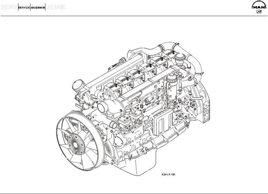
ENGINE DESCRIPTION D 2876 CR
Full general
The inline engines of the D 2876 LF series underwent major modification for the heavy-duty MAN Trucknology Generation (TGA):
New grading with college power and torque plus high torque gradients
Substantial improvement of engine efficiency and fuel consumption over wide ranges of the operating map through an increment of engine pinnacle force per unit area and the new common rails (CR) technique
Accommodation of the cylinder head, cylinder head packing, cylinder liner and creepo case bolt fit to the higher gas pressures
Reduced engine weight through omission of the secondary acoustic measures and utilize of a lighter crank case yoke
Apply of the 2d-generation Bosch common rail injection organisation (1600 bar)
Engine management by EDC 7 and communication with the vehicle management estimator on the CAN bus
Depending on weather condition of use and lubricants, oil change intervals of maximally 100,000 km tin be achieved and thus lower operating costs for the user
High reliability through adherence to the proven D 2876 LF 12.8 liter engine concept
Increase of frazzle brake performance in conjunction with the upgraded, force per unit area-controlled exhaust valve brake (EVB) as special equipment
Further increase of exhaust restriction operation through utilize of the entirely new, innovative primary braking system water retarder (PriTarder) in conjunction with the pressurecontrolled EVB equally special equipment
| D:\Automobile\TRUCK\Homo\MAN Serial\Двигатель_Топливная система\Двигатели\en\D2876_CR_eng.doc | Page five |

Changes compared to before D 28.. Euro three engines
| Engine | Water pump |
| Crank case | MAN PriTarder |
| Crank shaft | Fan bearing |
| Connecting rods | Visco fan Eaton |
| Pistons | |
| Cylinder liners | Common rails injection organisation |
| Cylinder heads | EDC 7 |
| Cylinder head packing | Injectors (7-jet) |
| Rocker arm case with rocker arm | High-pressure pump with rail distribution |
| Frazzle manifold packing | Sensor technology |
| Oil pump | New fuel connector arrangement |
| Oil circulation |
| D:\Auto\TRUCK\MAN\Human being Serial\Двигатель_Топливная система\Двигатели\en\D2876_CR_eng.doc | Page half dozen |
D 28.. EURO 3 Common Track
| D:\Car\TRUCK\Human\Human Serial\Двигатель_Топливная система\Двигатели\en\D2876_CR_eng.doc | Folio vii |

ENGINE RANGE
| Engines | Series | Horsepower rating | Chassis number | |
| (ISO 1585-88195 EEC) | starting with: | |||
| D 2876 LF 12.............. | Euro iii | ................................TGA......................... | 480 hp / 353 kW.................................... | WMAH.. |
| D 2876 LF 13.............. | Euro 3................................ | TGA......................... | 530 hp / 390 kW.................................... | WMAH.. |
| D:\Automobile\TRUCK\Human\Man Serial\Двигатель_Топливная система\Двигатели\en\D2876_CR_eng.doc | Page viii |

GENERAL Caption OF Blazon DESIGNATION
Example TGA 26o530
| T | Trucknology |
| Chiliad | Generation |
| A | -vehicle weight to a higher place 18 tons |
| 26 | Overall weight in t |
| 530 | Horsepower figure without Euro standard specification |
| D:\Auto\TRUCK\Homo\MAN Serial\Двигатель_Топливная система\Двигатели\en\D2876_CR_eng.doctor | Page 9 |

EMISSIONS – Frazzle GAS FIGURES
In Europe the 13-stride test to ECE R49 is used for commercial vehicles of more than 3.five t permissible overall weight.
This ways measuring the engine'due south exhaust emissions in thirteen ready defined, stationary operating states.
Then the hateful emissions are calculated.
In the procedure for Euro 3 engines, in contrast to Euro 2, measurements will probably likewise exist conducted in the subdynamic and, depending on the engine version, in the full dynamic state.
| 1993 | 1996 | 2000 | ||
| Pollutants | Euro one | Euro ii | Euro three | |
| CO | v | iv | 2 | |
| Carbon monoxide | ||||
| HC | i.25 | 1.1 | 0.half dozen | |
| Hydrocarbons | ||||
| NOx | ix | 7 | five | |
| Nitrogen oxide | ||||
| Particles | 0.4 | 0.15 | 0.1 | |
Exhaust gas figures in g/kW/h
| D:\Car\TRUCK\MAN\MAN Series\Двигатель_Топливная система\Двигатели\en\D2876_CR_eng.md | Page 10 |
![]()
EXTRA EQUIPMENT
The following actress equipment is possible depending on how the customer intends to use a vehicle:
Gear wheel driven power takeoff at engine end with 600 Nm (temporarily 720 Nm) torque
Refrigerant condenser, driven by Poly V-chugalug, firmly attached to intermediate case, for vehicles with air-conditioning
Possibility of calculation hydro geared pump to cam shaft power takeoff
Possibility of adding steering pumps and hydraulic pumps on air compressor forepart and rear
Cooling water preheater from Calix (220 V, 1100 W)
Ready for attachment of Frigoblock generators G12/G17/G24 (WR is not possible hither)
MAN PriTarder combination of water retarder and EVB-ec
| D:\Auto\TRUCK\MAN\MAN Serial\Двигатель_Топливная система\Двигатели\en\D2876_CR_eng.doc | Folio xi |

Explanation OF ENGINE CODE
ENGINE Type Characterization
Human being - Werk Nürnberg
| Typ | D 2876 LF 12 | ||
| Motor-Nr. / Engine-no | N I / Northward II | ||
| 2120025200B2E1 | P1 | ||
Box N I / N II
I Deviation of 0.one mm
II Deviation of 0.25 mm
P Large-end begetting pin
H Crank shaft bearing pivot
South Follower of cam shaft (S1 0.25 mm vanquish)
Engine type designation
D 2876 LF 12
| D ........... | Diesel fuel | |
| 28.......... | +100 = bore bore, due east.chiliad. 128 mm | |
| 7............ | Stroke: half-dozen = 155 mm, seven = 166 mm | |
| six............ | Number of cylinders: 6 = 6-cylinder, 0 = ten-cylinder, | |
| 2 = 12-cylinder | ||
| 50............ | Turbo charger with intercooler | |
| F............ | Engine incorporation: | |
| F | Truck, forward control, vertical engine | |
| OH | Autobus, rear-engined, vertical | |
| UH | Bus, rear-engined, horizontal | |
| 12.......... | Engine variant, particularly of import for | |
| procuring spare parts, | ||
| technical data and settings | ||
| D:\Auto\TRUCK\MAN\Human being Series\Двигатель_Топливная система\Двигатели\en\D2876_CR_eng.doc | Page 12 |

ENGINE IDENTIFICATION NUMBER
Example:
| 212 | 0025 | 200 | B two | E ane | ||||||||||||||||
| A | C | |||||||||||||||||||
| B | D Due east | F G | ||||||||||||||||||
| T287602 | ||||||||||||||||||||
| A......... | 212.............. | Engine type code | ||||||||||||||||||
| B......... | 0025............ | Date of assembly | ||||||||||||||||||
| C......... | 200.............. | Assembly sequence (progress effigy on date of assembly) | ||||||||||||||||||
| D......... | B ................. | Overview flywheel | ||||||||||||||||||
| E......... | ii.................. | Overview injection pump/regulation | ||||||||||||||||||
| F ......... | E.................. | Overview air compressor | ||||||||||||||||||
| G......... | one.................. | Special equipment similar engine-governed ability takeoff | ||||||||||||||||||
| D:\Auto\TRUCK\Human\MAN Series\Двигатель_Топливная система\Двигатели\en\D2876_CR_eng.physician | Page 13 |

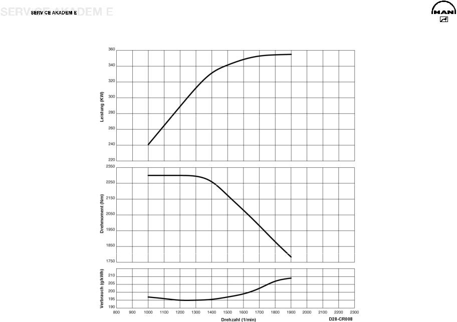
BASICS OF TORQUE
A TORQUE C SPECIFIC FUEL CONSUMPTION
Power and torque increase with speed. After overcoming the friction loss and greater heat losses at depression speeds, the engine achieves its maximum torque with optimum filling of the cylinder. If speed increases further, the torque drops because of the greater menses resistance and brusk valve opening times.
The full-load consumption curve in the diagram tin be explained by the fact that you get less than good fuel consumption in the low range of speed because of the poor force per unit area mix of the fuel particles (14.five:1). At high speeds, combustion is imperfect because of the curt time that is available. And fuel consumption increases.
B POWER
Ability is the product of speed and torque. Seeing as the drop in torque is slower than the increase in speed, there is initially an increment if the power output of an engine. Betwixt the maximum torque and the maximum power there is an elastic range in which power is kept constant by increasing torque although the speed is dropping.
| D:\Auto\TRUCK\Man\Man Series\Двигатель_Топливная система\Двигатели\en\D2876_CR_eng.doc | Page 14 |

| D:\Auto\TRUCK\Human\MAN Series\Двигатель_Топливная система\Двигатели\en\D2876_CR_eng.md | Page xv | ||||||||

TECHNICAL DATA
| D 2876 LF 12 Euro 3 | |||
| Model.............................................................. | R6 TI-EDC (4 V) | Idling speed .............................................................. | 600 i/min |
| Cylinder arrangement................................... | 6 cylinders inline | Valve play on cold engine....................................... | Four 0.fifty mm |
| Max. power ..................................................... | 353 kW / 480 hp | Valve play exhaust with EVB .............. | EV 0.80 mm / 0.threescore mm |
| Rated speed ........................................................... | 1900 1/min | Pinch pressure................................................. | > 28 bar |
| Max. torque................................................................. | 2300 Nm | Admissible force per unit area divergence between cylinders..max. iv bar | |
| Speed at max. torque................................. | k to 1300 1/min | Coolant ........................................................... | 50 (I/R 58) liters |
| Capacity.................................................................. | 12,816 cmiii | Oil charge .................................................................... | 42 liters |
| Bore / stroke ............................................................... | 128 / 166 | Fuel arrangement......................................................... | Bosch EDC seven |
| Ignition sequence ................................................... | 1-5-3-half-dozen-two-4 | Fan coupling actuation........................................ | hydroelectric |
| Cylinder 1 location....................................................... | fan side | Weight (dry) with WR................................................... | 1071 kg |
| Combustion process, injector ............................................ | 7-jet | K factor........................................................................... | 1.3 m-one |
| Compression.......................................................................... | eighteen | ||
| D:\Auto\TRUCK\Homo\Homo Series\Двигатель_Топливная система\Двигатели\en\D2876_CR_eng.doc | Page 16 |
| D:\Auto\TRUCK\MAN\MAN Series\Двигатель_Топливная система\Двигатели\en\D2876_CR_eng.doc | Page 17 | ||||||||

| D 2876 LF thirteen Euro 3 | ||||||||
| Model.............................................................. | R6 TI-EDC (iv Five) | Idling speed .............................................................. | 600 1/min | |||||
| Cylinder arrangement................................... | 6 cylinders inline | Valve play on common cold engine....................................... | 4 0.fifty mm | |||||
| Max. power ..................................................... | 390 kW / 530 hp | Valve play exhaust with EVB .............. | EV 0.lxxx mm / 0.60 mm | |||||
| Rated speed ........................................................... | 1900 1/min | Compression pressure................................................. | > 28 bar | |||||
| Max. torque................................................................. | 2400 Nm | Admissible force per unit area difference betwixt cylinders..max. 4 bar | ||||||
| Speed at max. torque................................. | m to 1400 one/min | Coolant ........................................................... | 50 (I/R 58) liters | |||||
| Capacity.................................................................. | 12,816 cm3 | Oil accuse .................................................................... | 42 liters | |||||
| Bore / stroke ............................................................... | 128 / 166 | Fuel arrangement......................................................... | Bosch EDC 7 | |||||
| Ignition sequence ................................................... | 1-5-3-6-2-four | Fan coupling actuation........................................ | hydroelectric | |||||
| Cylinder one location....................................................... | fan side | Weight (dry) without WR.............................................. | 1049 kg | |||||
| Combustion process, injector ............................................ | vii-jet | K cistron........................................................................... | ane.3 m-ane | |||||
| Compression.......................................................................... | xviii | |||||||
| D:\Automobile\TRUCK\MAN\MAN Series\Двигатель_Топливная система\Двигатели\en\D2876_CR_eng.doctor | Page xviii |

| D:\Auto\TRUCK\Human being\Homo Serial\Двигатель_Топливная система\Двигатели\en\D2876_CR_eng.dr. | Page 19 | ||||||||

ENGINE BLOCK – Creepo CASE
The crank case is cast in one slice together with the cylinder block from special GJL-250 bandage iron. The wet cylinder liners of highly wearable-resistant, special centrifugal cast GJL-250 are exchangeable. The sealing between the cylinder liner and the crank case coolant jacket at the top is by a oval elastomer moulded washer and at the bottom by ii elastomer round sealing rings.
Optimized wall thicknesses and functional ribbing of the crank instance side walls optimized by the finite element method (FEM) produce rigidity of form and depression racket emission.
The crank instance was matched to the college ignition pressure (160 instead of 145 bar) by reinforcing the partitions and geometrically optimizing the cylinder liner plumbing fixtures, but for the aforementioned crank example weight.
To amend the oil supply to the valve gear, actress oil holes were provided in the crank example across from the main oil duct through the partitions to the cam shaft bearing (and on to the valve gear).
The crank case was matched externally for meaty attachment of the new EDC 7 control unit, rail and cam shaft engine speed sensor. The casting and machining of the crank case were also optimized.
The crank case is closed off at the rear by the flywheel/timing case of GJS-400 ductile cast iron, with the rear crank shaft sealing band, and at the bottom by the crank example yoke of permanent mould cast aluminium (Loctite 518 sealing). Apply a track with a maximum width of 1 mm.
The creepo example venting gases are fed dorsum into the combustion air past way of a wire-knit oil trap with pressure regulating valve fastened to the rear left of the creepo example to avoid emission on the intake side of the turbo charger.
| D:\Motorcar\TRUCK\Homo\Human Series\Двигатель_Топливная система\Двигатели\en\D2876_CR_eng.md | Page 20 |
![]()
| D:\Auto\TRUCK\Homo\MAN Series\Двигатель_Топливная система\Двигатели\en\D2876_CR_eng.dr. | Page 21 | ||||||||

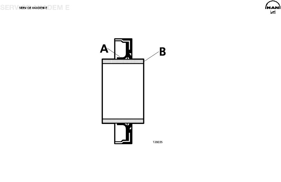
CYLINDER LINERS
The wet, exchangeable cylinder liners are produced from a special centrifugal cast atomic number 26.
The oval O-ring (one) for the upper packing must be inserted without whatever twist in the second grooves of the liner.
Lightly glaze the cylinder liner in the region of the upper O-ring with engine oil.
Place new O-rings (two) in the crank case (Viton).
Lightly glaze the region of the lower O-ring with engine oil, as well as the transition of the cylindrical part of the bush.
Circumspection:
Do NOT apply a brush!
NOTE:
The packing of the cylinder liners is different.
NOTE :
Practise Non Utilize ANY KIND OF GREASE / SEALANT.
Method for measuring cylinder liner project (without the sealing ring). Place cylinder liners in the creepo case without an O-ring.
Attach a press-on gauge plate and tighten to 40 Nm. Then measure at at least iv points with the dial gauge.
ane Cylinder liner
2 Creepo case
C Rim depth in crank instance
D Rim meridian of cylinder liner
D-C Projection of liner from crank instance
Cylinder liner projection: min 0.035 mm, max. 0.one mm
| Rim depth | C | seven.965 to 8.015 mm |
| Rim height of cylinder liner | D | 8.05 to 8.07 mm |
| D:\Machine\TRUCK\Human\MAN Series\Двигатель_Топливная система\Двигатели\en\D2876_CR_eng.doctor | Page 22 |

| D:\Auto\TRUCK\MAN\Human Serial\Двигатель_Топливная система\Двигатели\en\D2876_CR_eng.medico | Page 23 | ||||||||

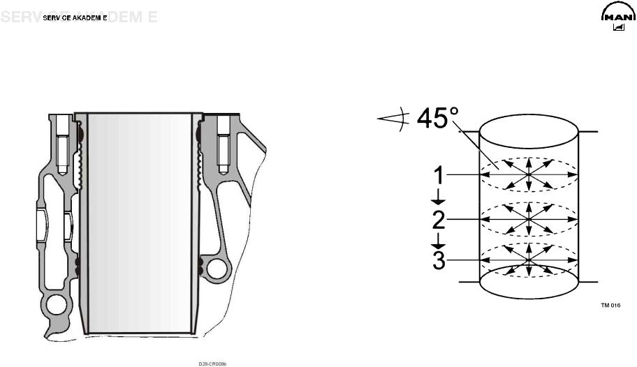
PISTON PLAY – CYLINDER LINERS
Measurement of piston play:
Measure the inner diameter of the cylinder liners with an inside micrometer at three levels from top to bottom, and radially at intervals of 45°. Read the piston diameter from the bottom of new pistons. On pistons that accept run, measure with an outer micrometer from the piston bottom edge beyond the piston axis. Decrease the piston diameter from the largest measured cylinder liner diameter.
The effigy arrived at is the piston play.
Notation:
If the piston play is too large, replace the cylinder bush and piston.
| Instance of piston play for D 28..LF | |
| Cylinder diameter...................................... | 127.99 to 128.01 mm |
| Piston diameter..................................... | 127.561 to 127.570 mm |
| Platonic play .......................................................... | 0.xiv to 0.xv mm |
| Wearable limit...................................................................... | 0.30 mm |
Mensurate on iii position, for example i,ii,iii
| D:\Motorcar\TRUCK\MAN\Homo Serial\Двигатель_Топливная система\Двигатели\en\D2876_CR_eng.md | Page 24 |
| D:\Auto\TRUCK\Homo\Man Series\Двигатель_Топливная система\Двигатели\en\D2876_CR_eng.md | Page 25 | ||||||||

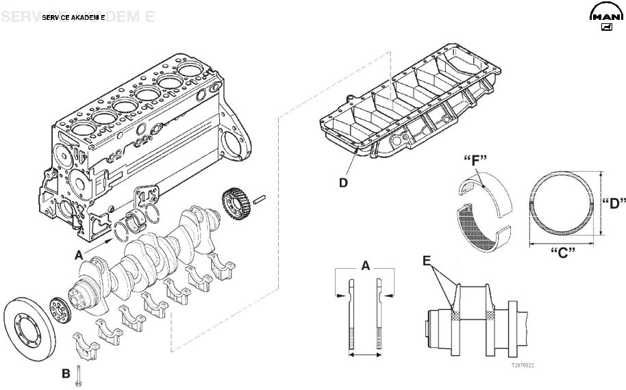
CRANK SHAFT
The creepo shaft has a 7-point bearing and eight forged-on counterweights to balance inertial forces. The main and big-stop bearing pins besides as the lapped bearing collars are consecration hardened and ground.
ON A CRANK SHAFT N1, ALL Large-Terminate OR Master Bearing PINS ARE IN EVERY Case Too N1.
The axial bearing of the crank shaft is implemented by thrust washers on the center bearing block.
Attention: The oil flutes of the thrust washers A must face the crank webs.
Attending: Never dismantle the vibration damper using a hammer or fitter'due south lever. The slightest paring will ruin the damping office of the vibration damper. This can cause clutch impairment and breakage of the crank shaft.
| A | Axial begetting of crank shaft............ | 0.190 to 0.312 mm |
| Clothing limit............................................................. | max. 1.25 mm | |
| B | Main bearing bolts.................................... | 300 Nm + 90° |
D Crank case yoke to reinforce crank case Employ 04.10394-9272 sealant.
E Designation H and P tolerance N or N1 of big-terminate or main begetting pins (N1= 0.ane mm deviation)
Spread of bearing shells F:
Measure dimension C.
Measure out dimension D.
Expansion = C minus D
Spread must be between 0.three and one.2 mm.
Attention: C must be greater than D.
| Main bearing pin bore .................... | N 103.98 to 104.00 mm |
| Main begetting inner diameter............. | Northward 104.066 to 104.112 mm |
| Other undersizes.................. | 0.25 to 0.50 mm, 0.75 to 1.00 mm |
| D:\Auto\TRUCK\MAN\MAN Series\Двигатель_Топливная система\Двигатели\en\D2876_CR_eng.md | Folio 26 |
| D:\Auto\TRUCK\MAN\Man Series\Двигатель_Топливная система\Двигатели\en\D2876_CR_eng.doc | Page 27 | ||||||||

Creepo shaft lining front and rear
On the rear crank shaft lining, like on the front, rotary shaft seals of polytetrafluorethylene (PTFE), trade name Teflon, are ever used.
Considering of its own relatively big initial tension, the lip (A) tends to curve inwards. For this reason the PTFE lining ring is supplied on a transport wrapper (B). It must exist left on this wrapper until it is used. Another reason for this is that the lip is very sensitive and the slightest damage tin can result in leakage. The sealing lip and the race of the flywheel must not exist coated with oil or other lubricants.
Notation:
New engines come without a race.
When repairing, only apply variants with a race (04.10160-9049 sealant).
Fitting notes:
The PTFE lining ring must be fitted absolutely free of oil
and grease. The slightest oil or grease traces on the race or lining ring can result in leakage.
Before fitting, clean any oil, grease and anti-corrosion agents off the race and pull-in tool. You can use any conventional cleaning agent for this purpose.
Never store the PTFE lining band without the supplied transport wrapper. Later but about 20 min without the wrapper it will lose its initial tension and is then unusable.
| D:\Auto\TRUCK\MAN\MAN Series\Двигатель_Топливная система\Двигатели\en\D2876_CR_eng.medico | Folio 28 |
| D:\Auto\TRUCK\MAN\Homo Serial\Двигатель_Топливная система\Двигатели\en\D2876_CR_eng.doc | Page 29 | ||||||||

Pull out the rotary shaft seal
Loosen the lining band by tapping information technology.
Use the extractor tool
Slide the iv hooks under the lip, plough through 90° then that they grip the ring backside the lip, and pull out the rotary shaft seal by turning the spindle.
Adhere the race
The latest crank shafts come without races. A race is fitted when renewing the crank shaft sealing ring.
Clean the inside of the race and creepo shaft stump, and coat the crank shaft stump with 04.10160-9049 sealant. Slide the race and printing-fit sleeve onto the adapter. Tighten the spindle in the adapter with the nut. Screw the adapter tightly to the crank shaft. The adapter must fit tightly on the crank shaft to ensure the right press-fit depth of the race. Pull in the race as far as the end of the press-fit sleeve.
Fit the rotary shaft seal
Screw the adapter to the crank shaft.
Clean the adapter and the race. The rotary shaft seal must be
assembled dry . Do not coat the lips with oil or other
lubricants.
Place the rotary shaft seal with the send wrapper on the adapter and slide the seal onto the adapter.
Remove the transport wrapper.
Slide the winding sleeve onto the adapter.
Screw the spindle into the adapter.
Pull in the rotary shaft seal equally far as the stop of the winding sleeve on the end cover.
| D:\Auto\TRUCK\Man\Human being Serial\Двигатель_Топливная система\Двигатели\en\D2876_CR_eng.doc | Folio 30 |
![]()
| D:\Auto\TRUCK\Human being\Homo Serial\Двигатель_Топливная система\Двигатели\en\D2876_CR_eng.md | Folio 31 | ||||||||

FLYWHEEL
The flywheel is centered on the crank shaft by a prepare pin and
attached by ten torque screws.
Tightening method for flywheel screws
Anti-fatigue screws M16 x 1.5 (12.9)
Pretighten to 100 Nm.
Turn xc0.
Tighten finally by turning 90°.
Non reusable
Caution:
Brand sure the race (two) is properly seated.
Use 04.10160-9049 sealant.
Place the faced side start and utilize a mandrel to push button information technology right on. Coat the seat of the race with greenish Omnifit.
Clutch shaft guide bearing (1)
| D:\Auto\TRUCK\Human\MAN Serial\Двигатель_Топливная система\Двигатели\en\D2876_CR_eng.md | Page 32 |

| D:\Car\TRUCK\Human being\MAN Serial\Двигатель_Топливная система\Двигатели\en\D2876_CR_eng.md | Page 33 | ||||||||

Machining of flywheel
In the result of heavy scoring, the permissible fabric clothing of the printing-on surface is max. 1,6 mm.
Minimum dimension A: 60.v mm
Standard dimension A: 62 ±0.one mm
Maximal lateral runout of starter rim: 0.5 mm
Outer diameter of flywheel: 488 to 487.eight mm
The starter rim is heated to betwixt 200 and 230°C for
assembly.
| D:\Auto\TRUCK\Human\Homo Series\Двигатель_Топливная система\Двигатели\en\D2876_CR_eng.medico | Page 34 |

| D:\Auto\TRUCK\Human being\Human being Series\Двигатель_Топливная система\Двигатели\en\D2876_CR_eng.medico | Page 35 | ||||||||

CONNECTING ROD
The connecting rods are drop-forged from oestrus-treatable C38mod steel, without weight compensating battens, and split obliquely by cracking the bearing cap. The oblique split simplifies assembly and repair, because the connecting rods tin can be taken out through the top of the cylinders.
The big-stop bearings are designed for extremely high stress and long service life. The upper bearing crush consists of highly wearable-resistant sputter metal. There is a long oil hole from the big to the small connecting rod eye for proper supply of oil to the latter.
Measurement of large-stop bearing
Measure the inner bore of the large-terminate bearing shells in an assembled state on the axes one, 2 and 3 and at levels a and b. Bearing shells whose diameter is within tolerance limits tin can be reused, if they are outside you must renew the bearing.
Chip them if the bore is larger or oval.
Notation:
The peak bearing crush is marked Elevation or has a red spot on the side (tempered backing shell).
| Big-end bearing pin dia. (standard).......... | 89.980 to xc.000 mm |
| Big-cease bearing inner dia. (standard)....... | xc.060 to xc.102 mm |
| Big-finish begetting spread (Miba) ......................... | 95.v to 96.4 mm |
| Large-end bearing radial play........................... | 0.060 to 0.122 mm |
| Spread C........................................................... | 95.five to 96.iv mm |
Tightening torque of connecting rod screws:
100 Nm+ten + 90°+10
Connecting rod screws: M14 x ane.5 x 65/10.9 Torx
Re-employ of the screws is non permissible.
Caution:
Practice Non place the connecting rod or the comprehend on the seam. Any harm (change) to the structural fracture volition destroy it.
| D:\Auto\TRUCK\MAN\MAN Serial\Двигатель_Топливная система\Двигатели\en\D2876_CR_eng.doc | Page 36 |

| D:\Auto\TRUCK\MAN\MAN Series\Двигатель_Топливная система\Двигатели\en\D2876_CR_eng.doc | Folio 37 | ||||||||

PISTONS
The three-ring pistons are of a special bandage aluminium with a moulded ring insert for the uppermost piston ring. The combustion chamber is slightly retracted, graduated and omega-shaped. There are valve recesses on the inlet and outlet side. To reduce the effects of estrus, the pistons have a cast integral cooling duct and are cooled past an oil jet from injection nozzles.
The pistons were adapted to the higher ignition pressures past graduated bracing of the connecting rod, suitable option of materials and appropriate scaling of the combustion chamber.
The oil injection nozzles in the crank case are matched in their flow cross-section to the new cooling duct of the pistons. The oil force per unit area valve in the injection nozzles is omitted to ensure proper piston cooling too at depression engine speeds.
A new, smooth piston pivot of larger bore is used to take load off the piston pin boss.
Rings
Double-faced trapezoidal band and 2nd compression ring as compression rings, ventilated oil scraper band with spiral expander and bevelled outer edges.
Piston projection nether/over meridian border of crank case:
-0.03 to +0.331 mm
Gap of piston rings, wear limit
I Trapezoidal ring, wear limit ane.5 mm
2 Second pinch band, clothing limit one.5 mm Iii Oil scraper ring, wear limit 1.5 mm
| D:\Auto\TRUCK\Human being\MAN Series\Двигатель_Топливная система\Двигатели\en\D2876_CR_eng.doc | Folio 38 |

| D:\Automobile\TRUCK\MAN\MAN Series\Двигатель_Топливная система\Двигатели\en\D2876_CR_eng.doc | Page 39 | ||||||||

Pistons (technical data from Kolben Schmidt)
ane Piston diameter, measured across boss:
KS measured 20 mm
| higher up piston bottom edge (2)......... | 127.561 to 127.570 mm |
| iv Compression pinnacle: | |
| Standard dimension: D 2876 LF........................... | 79.25 mm |
Undersize: 0.two mm / 0.iv mm / 0.six mm
A Piston projection under/over crank case top edge:
- 0.03 to +0.30 mm
| Piston ring flutes | ||
| (5) | Pinch ring ane | .........................................4 to iv.05 mm |
| (6) | Compression ring 2 .................................... | 3.04 to three.06 mm |
| (vii) | Oil scraper band.......................................... | 4.04 to iv.06 mm |
| Piston ring superlative | |
| Double-faced trapezoidal pinch ring | |
| Height....................................................... | 3.99 to 4.025 mm |
| Gap............................................................. | 0.35 to 0.55 mm |
| 2nd compression ring ................................... | 2.97 to iii.0 mm |
| Gap................................................................. | 0.vii to 0.nine mm |
| Oil scraper ring | |
| KS............................................................. | three.975 to 3.99 mm |
| Gap............................................................. | 0.25 to 0.55 mm |
| Piston weight difference per engine set...................... | max. 50 thousand |
Fit with arrow pointing to the frontend
| D:\Automobile\TRUCK\MAN\Man Series\Двигатель_Топливная система\Двигатели\en\D2876_CR_eng.doc | Page 40 |
![]()
| D:\Automobile\TRUCK\Human being\Human being Serial\Двигатель_Топливная система\Двигатели\en\D2876_CR_eng.doc | Page 41 | ||||||||

ENGINE CONTROL
Setting of timing
The marking of the crank shaft gear must match with the marking of the compress-fit cam shaft gear (not the same as TDC of cylinder 1).
| A | Gear wheels on flywheel side | B | Gear wheels on fan side |
| 1 | Crank shaft | viii | Cam shaft bike |
| ii | Oil pump drive | ix | Compressor bulldoze gear |
| 3 | Oil pump delivery wheels | 10 | Fan bulldoze gear |
four Cam shaft
5 Intermediate gear for high force per unit area pump
6 High pressure level pump bulldoze
7 Auxiliary drive
| D:\Auto\TRUCK\Human\MAN Series\Двигатель_Топливная система\Двигатели\en\D2876_CR_eng.doc | Page 42 |

| D:\Automobile\TRUCK\Human being\MAN Serial\Двигатель_Топливная система\Двигатели\en\D2876_CR_eng.doc | Page 43 | ||||||||

CAM SHAFT
The cam shaft is forged from Cf53 steel with induction hardened and ground cams and bearing points. It is seated in the crank case with a 7-betoken bearing in white metal bushes. The centric bearing of the cam shaft takes the grade of a neckband end bearing in the creepo case on bearing vii. In the timing case there is a butting band screwed in equally an axial finish.
Engines with cam shaft ability takeoff are fitted with a peculiarly forged shaft of carburizing 16MnCr5 steel with a highly wearresistant, sputter neckband end bearing 7 in the creepo case.
The cam shaft is driven from the crank shaft by case-hardened, helically toothed spur wheels on the rear side of the engine. Bolted at the dorsum of the cam shaft is besides the drive bicycle for loftier-pressure level pump CP3.iv (M10 10 35 10.ix Nm 65). This gear wheel bears markings for the cam shaft engine speed sensor. Valve lifter lubricant paste 09.15011-0011.
A spur wheel is fitted to the front of the cam shaft to drive the air compressor and the fan shaft.
1 Reference markers to place showtime cylinder
two High-pressure pump drive wheel
3 Cam shaft bulldoze wheel
iv Retaining screw 65 Nm
5 Oil hole
| D:\Automobile\TRUCK\MAN\Man Series\Двигатель_Топливная система\Двигатели\en\D2876_CR_eng.md | Folio 44 |

| D:\Auto\TRUCK\MAN\MAN Series\Двигатель_Топливная система\Двигатели\en\D2876_CR_eng.doc | Page 45 | ||||||||

| Admissible play of cam shaft | |||||||
| Cam shaft centric play ....................................... | 0.20 to 0.90 mm | ||||||
| Wear limit ................................................................... | 1.50 mm | ||||||
| Examination without the air compressor attached. | |||||||
| NOTE: | |||||||
For cam shaft ability takeoff, the cam shaft is held reinforced betwixt bearings 6 and vii and in a highly wear-resistant, special collar finish bearing on begetting 7.
Tightening torque:
Screws for butting ring 40 Nm
Secure with Loctite 648.
Measure the axial play of the cam shaft.
Printing the cam shaft tightly confronting the crank case.
Add the seal thickness z = 0.five mm to dimension y.
Cam shaft centric play = y + z - 10
Dimension x = margin of sealing face of creepo case to butting face of cam shaft bulldoze wheel
Dimension y = margin of sealing confront of timing case to butting ring
Dimension z = thickness of seal pressed
i Crank case
2 Gauge rail
three Cam shaft gear bicycle
iv Sealing face of crank instance
five Sealing face up of timing case
half-dozen Butting ring
7 Timing instance
| D:\Auto\TRUCK\MAN\MAN Serial\Двигатель_Топливная система\Двигатели\en\D2876_CR_eng.dr. | Page 46 |

| D:\Machine\TRUCK\Homo\MAN Serial\Двигатель_Топливная система\Двигатели\en\D2876_CR_eng.md | Page 47 | ||||||||

Check OF VALVE TIMING
Check the timing for the specified valve bike.
Twisting of the shrink-fit cam shaft bulldoze wheel tin result in serious engine impairment.
Consequently, after engine malfunctions that can cause such twisting, eastward.grand. failure of the air compressor, make sure seating is right by checking the valve timing.
Requirement: push button roads must not be bent.
| D 2876 LF 12 | 0.50 IV / 0.60 | EV / 0.40 EVB Valve play |
| Valve travel | 9.0 to nine.5 mm | |
| D 2876 LF 13 | 0.l Iv / 0.60 | EV / 0.40 EVB Valve play |
| Valve travel | 9.0 to 9.five mm |
Proceed every bit follows:
Adhere the engine turning gear to the timing example.
Remove the cylinder caput.
Correctly ready the inlet and exhaust valves.
Ready the flywheel to TDC so that the valves overlap.
Place the punch guess with approx. 11 mm advance on the disk of the inlet valve on the quaternary cylinder and set up to "O".
Plough the engine in the running direction (left) until the dial estimate pointer no longer moves.
If the timing is correct, the figures shown on the dial gauge must be within the following tolerances. Read the valve travel from the punch approximate.
.
| D:\Auto\TRUCK\Human\MAN Series\Двигатель_Топливная система\Двигатели\en\D2876_CR_eng.doc | Page 48 |

| D:\Auto\TRUCK\Human being\Human Serial\Двигатель_Топливная система\Двигатели\en\D2876_CR_eng.dr. | Page 49 | ||||||||

Timing
| Timing D 2876 LF 12/thirteen | Timing diagram | |||
| Inlet opens | 23° before TDC | Degrees referred to creepo shaft bending | ||
| Inlet closes | 12° subsequently BDC | |||
| Exhaust opens | 60° before BDC | 1 = | Direction of engine turning | |
| Exhaust closes | 30° later on TDC | 2 | = | Inlet opens |
| 3 | = | Inlet closes | ||
| 4 | = | Inlet opening time | ||
| 5 | = | Center inlet cam | ||
| half dozen | = | Exhaust opens | ||
| 7 | = | Exhaust closes | ||
| 8 | = | Frazzle opening time | ||
| 9 | = | Center exhaust cam | ||
| D:\Auto\TRUCK\MAN\Homo Series\Двигатель_Топливная система\Двигатели\en\D2876_CR_eng.dr. | Page fifty |
montejanohateardideft66.blogspot.com
Source: https://manualmachine.com/man/d2876lf12/4535793-service-manual/
0 Response to "Chevy Truck 2006 Ammeter Reading 14v at Idle"
Post a Comment